
16kW Inverter Battery Compatibility: 7 Checks for Installers (2026)

Amanda Gee
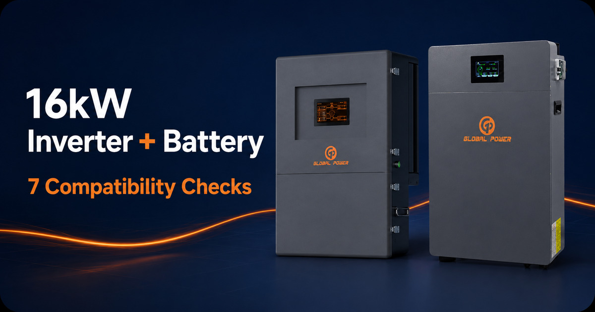
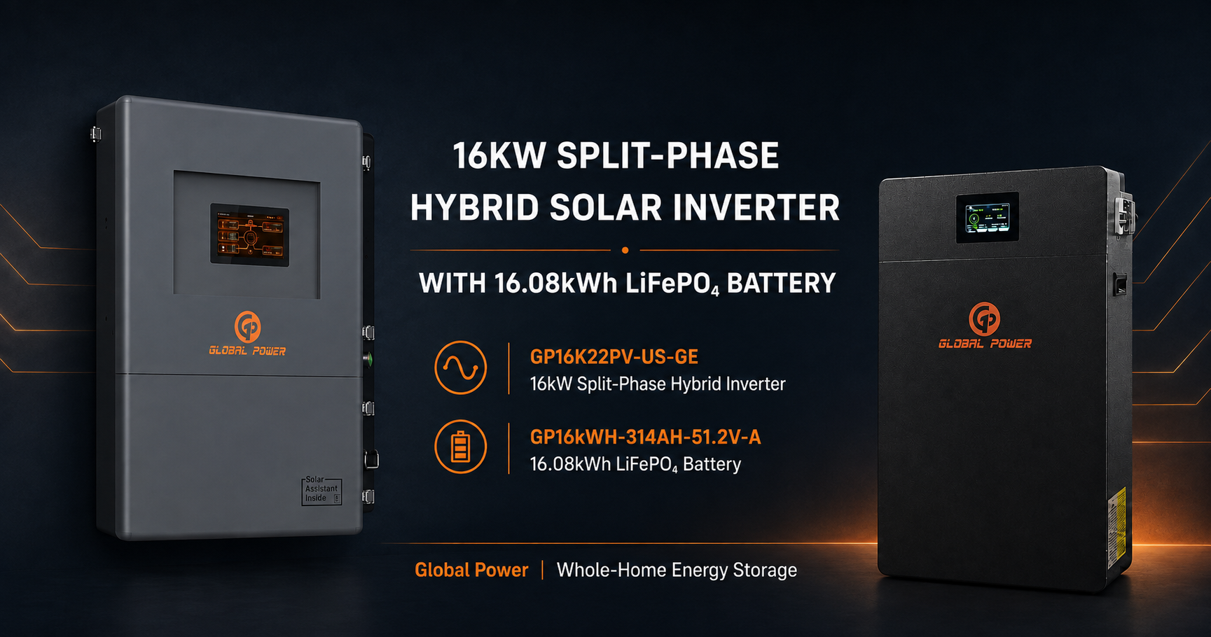
Quick answer: The GP16K22PV-US-GE and GP16kWH-314AH-51.2V-A have overlapping published voltage ranges: 42–60 VDC for the inverter and 47.5–57.6 VDC for the battery. However, one battery is rated for 10.2 kW continuous discharge, below the inverter’s 16 kW output. Final sizing must also verify BMS communication, current limits, starting loads, runtime, protection, and local requirements.
Review the exact products used in this guide:
- View the GP16K22PV-US-GE 16kW split-phase hybrid inverter
- View the GP16kWH-314AH-51.2V-A 16.08kWh LFP battery
- Request an installer compatibility review
This installer-first guide uses the current Global Power inverter datasheet and the English specification sheet for the GP16kWH-314AH-51.2V-A as its primary technical sources. It does not use the visually different IP65 battery model as the promoted product. Solar Assistant is an optional Raspberry Pi monitoring solution; it is not built into every inverter and does not replace BMS compatibility confirmation.
Quick Guide: How to Check 16kW Inverter Battery Fit in 7 Steps
- Identify the exact equipment — Record the GP16K22PV-US-GE inverter and GP16kWH-314AH-51.2V-A battery model, plus hardware, firmware, and document revisions.
- Verify the voltage window — Compare the inverter's 42–60 VDC input range with the battery's recommended 47.5–57.6 VDC range, 56–57 VDC charge range, and 47.5 VDC discharge cut-off.
- Calculate usable energy — Start with 16 kWh per battery and the published recommended 80% DoD, giving approximately 12.8 kWh per battery before conversion and system losses.
- Check continuous and charging current — Use 157 A as the recommended charge/discharge current, 157 A as maximum continuous charge current, and 200 A as maximum continuous discharge current.
- Confirm BMS communication — Verify the CAN or RS485 protocol, pinout, cable, settings, firmware, and exact approved configuration before sign-off.
- Account for generator input and site starting loads — Verify generator controls, ratings, transfer requirements, and measured or documented starting loads.
- Review installation and approval requirements — Treat the battery as an IP20 indoor product, confirm temperature limits, protection, clearances, parallel configuration, and AHJ requirements.
Published Datasheet Values for the GP16K22PV-US-GE and GP16kWH-314AH-51.2V-A
Compatibility conclusion: The published voltage ranges overlap. The battery datasheet lists 10.2 kW continuous discharge power, which is below the inverter’s 16 kW rated output. Final battery-bank sizing and system approval require the project’s continuous load, starting load, energy requirement, approved current limits, confirmed BMS communication, protection design, and the current revision of both product datasheets.
| Item | Published value | Installer interpretation |
|---|---|---|
| Inverter | GP16K22PV-US-GE; 16,000 W / 16,000 VA; 120/240 V split-phase; the datasheet also lists 120/208 V | 16 kW is the continuous rated output. Confirm the applicable 120/208 V configuration, and compare the published surge power and duration with motor and compressor starting loads. |
| Promoted battery | GP16kWH-314AH-51.2V-A; LiFePO4; 51.2 V; 314 Ah; 16 kWh | Use the current GP16kWH-314AH-51.2V-A English datasheet revision for all settings. Inventory status is commercial information, not a technical rating. |
| Voltage limits | Inverter input: 42–60 VDC; battery recommended range: 47.5–57.6 VDC; charge: 56–57 VDC; discharge cut-off: 47.5 VDC | Voltage-window overlap is necessary but does not by itself approve compatibility. Confirm the BMS protocol and manufacturer-approved charge, low-voltage cut-off, and protection settings. |
| DoD and cycle life | Recommended DoD: 80%; 8,000 cycles at 0.5C, 25°C, 80% DoD, to 70% end-of-life capacity | Cycle life is a laboratory rating under the stated test conditions, not guaranteed field life or a warranty commitment. |
| Battery current | Recommended charge/discharge: 157 A; maximum continuous charge: 157 A; maximum continuous discharge: 200 A | Use the lowest applicable limit among the inverter setting, per-battery BMS limit, battery-bank limit, conductor ampacity, and overcurrent protection. |
| Continuous battery power | Charge: 8 kW; discharge: 10.2 kW | At 51.2 V and 200 A, the nominal DC limit is about 10.2 kW. Available AC power is lower after inverter losses and falls as battery voltage decreases. |
| Inverter charging current | Inverter maximum battery-charging current: 250 A | Limit the inverter charge setting to the approved battery-bank charge current; for one battery, do not exceed 157 A continuous charge. |
| Parallel capability | Battery: maximum 15 units; inverter: maximum 6 units | These are published maximums, not recommended project quantities. Confirm BMS addressing, communication, busbar design, individual protection, conductor sizing, and current sharing. |
| Efficiency | Battery round-trip efficiency: 95%; inverter peak efficiency: 97.5% | The technical table identifies 95% as battery round-trip efficiency. This is a battery-level datasheet value, not a guaranteed whole-system efficiency; use a conservative verified system factor for runtime estimates. |
| Temperature | Battery charge: 0–50°C; discharge: –20–55°C | Use these conservative technical-table limits until the wider values shown elsewhere in the battery document are formally harmonized. |
| Protection rating and mounting | Battery: IP20, wall/floor mount; inverter: IP65 | Install the battery indoors in a suitable controlled environment; do not treat it as the IP65 battery model. |
| BMS and interfaces | Integrated active-balancing BMS; CAN and RS485 listed in the technical table | Confirm protocol, pinout, cable, firmware, termination, addressing, and settings for this exact pairing before commissioning. |
| Physical and protection data | 500 × 780 × 250 mm; 128 kg; 250 A DC breaker | Verify the current drawing revision and supplied unit before structural, clearance, conductor, and overcurrent-protection design. |
How to Verify Battery Fit for the GP16K22PV-US-GE
Identify the Exact Models and Documentation
Confirm that the inverter is GP16K22PV-US-GE and the A-model battery is GP16kWH-314AH-51.2V-A. This article does not promote the visually different IP65 battery model. Retain the current inverter datasheet, the A-model English specification sheet, wiring and communication documentation, installation instructions, and any manufacturer compatibility statement.
If the product page, label, or another document conflicts with the A-model English specification sheet, pause design approval and obtain written clarification from Global Power. In this guide, the A-model English specification sheet controls the technical values.
Verify the Operating-Voltage Window
The inverter datasheet publishes a 42–60 VDC battery input range. The A-model battery specification publishes a recommended 47.5–57.6 VDC operating range, a 56–57 VDC charge range, and a 47.5 VDC discharge cut-off. The battery range sits inside the inverter range, supporting voltage-window compatibility for this exact pairing.
Voltage overlap alone is not a complete compatibility approval. Confirm programmed charge and discharge limits, low- and high-voltage protection behavior, BMS communication, firmware, cabling, and the exact equipment revisions before commissioning.
Calculate Usable Energy With the Published 80% DoD
The A-model battery is rated at 16 kWh. Using its recommended 80% DoD gives approximately 12.8 kWh of usable battery energy per unit before inverter and other system losses.
Usable battery energy (kWh) = N × 16 kWh × 0.80
For a system-level estimate, use runtime (hours) = (N × 16 kWh × 0.80 × η) ÷ L, where N is battery count, η is a conservative verified system-efficiency factor, and L is the measured or documented average load in kW. Do not present the result as guaranteed runtime.
Check Continuous, Charging, and Starting Current
The GP16K22PV-US-GE is rated at 16,000 W / 16,000 VA. The A-model battery specifies 157 A recommended charge/discharge current, 157 A maximum continuous charge current, 200 A maximum continuous discharge current, 8 kW continuous charge power, and 10.2 kW continuous discharge power. The inverter can be capable of more charging current than one battery accepts, so its charge limit must be programmed to the lower approved battery or bank limit.
Use the project's verified continuous and starting loads, then compare the calculated battery-side demand with the approved battery and inverter limits. A useful design relationship is:
Estimated battery current (A) = Pbatt ÷ (Vbatt × η)
In this formula, Pbatt is verified battery-side power in watts, Vbatt is verified battery voltage, and η is verified conversion efficiency. Compare the result with the manufacturer-approved continuous and peak limits for each battery and the bank.
For starting loads, use Pstart or Istart from the equipment documentation or site measurement. Do not substitute a generic HVAC wattage, motor multiplier, or assumed transient value.
Confirm BMS Communication Before Commissioning
The battery technical table lists CAN and RS485 communication, and the inverter supports battery communication. The exact protocol, pinout, cable, termination, register map, firmware, and settings for this pairing must still be confirmed before commissioning.
During commissioning, confirm that the inverter recognizes the intended battery, receives the required status and protection information, and applies the approved charge and discharge controls. Save commissioning evidence with the project records.
Solar Assistant can be used as an optional Raspberry Pi monitoring solution where the installation supports it. It is not built into every Global Power inverter, and it does not establish battery compatibility by itself.
Account for Generator Input and Site Starting Loads
Generator input is supported on the GP16K22PV-US-GE. Before finalizing the design, verify the generator's electrical characteristics, control interface, transfer sequence, grounding arrangement, protection requirements, and permitted charging behavior against the current documentation and the project design.
For HVAC, well pumps, compressors, and other motor loads, use the verified running load and verified starting requirement for the equipment at the site. Replace generic examples with the project's actual values:
Required stored energy (kWh) = L × H ÷ η
In this formula, L is the verified site load in kW, H is the required backup duration in hours, and η is the verified system usable-efficiency factor. Compare that requirement with the usable-energy formula above and separately confirm that Pstart or Istart stays within the approved inverter and battery limits.
Review Installation, Temperature, Parallel, and Protection Requirements
The inverter operating range is –25°C to 60°C. For the A-model battery, use the technical-table limits of 0–50°C for charging and –20–55°C for discharging. The battery is IP20 and permits a maximum of 15 parallel units; the inverter is IP65 and permits up to 6 parallel units.
The A-model feature section shows wider battery temperature limits than its technical table. Use the conservative technical-table values until Global Power provides harmonized written guidance. Before release for construction, verify mounting, clearance, conductors, overcurrent protection, BMS addressing, and AHJ and utility requirements.
Installer Checklist Before Sign-Off
- Exact inverter and battery model numbers recorded.
- Current documentation revision dates checked.
- Operating-voltage window confirmed for both devices.
- Published recommended 80% DoD recorded and applied.
- Verified site running load and starting load documented.
- Battery-bank energy and current calculations completed.
- BMS protocol, pinout, cable, settings, and firmware requirements confirmed.
- Third-party battery compatibility confirmed in writing before use.
- Generator input, controls, and transfer requirements reviewed.
- Temperature, clearances, parallel limits, output behavior, and protection requirements verified.
- AHJ and utility requirements checked for the project location.
- Commissioning and monitoring plan documented, including whether optional Solar Assistant will be installed.
How Many Batteries Are Needed?
There is no single battery count for every 16kW inverter installation. Determine the count from both energy and current requirements, then apply the manufacturer's approved parallel limit.
Energy-based battery count: Nenergy = ceil(Erequired ÷ (16 kWh × D))
Current-based battery count: Ncurrent = ceil(Irequired ÷ Iapproved per battery)
Use the larger result, then check starting-current performance, charging limits, communication requirements, installation conditions, and the current parallel limit. The final count must come from the project data and current manufacturer documentation.
Can Third-Party Batteries Be Used?
This article does not claim that any third-party battery is compatible with the GP16K22PV-US-GE. A third-party battery should be considered only after protocol, pinout, firmware, voltage window, current limits, protection behavior, parallel operation, and written manufacturer approval have been confirmed for the exact models.
A shared nominal voltage or LiFePO4 chemistry is not enough to establish compatibility. If protocol confirmation is unavailable, do not represent the battery as compatible.
Still comparing system options? Review the 2026 Split-Phase Hybrid Solar Inverter Buyer’s Guide for inverter sizing factors, generator integration, monitoring, battery expansion, and installer-focused feature comparisons.
GP16K22PV-US-GE and GP16kWH-314AH-51.2V-A Compatibility Snapshot
| Check | Published fact | Installer action |
|---|---|---|
| Voltage | Inverter 42–60 VDC; battery 47.5–57.6 VDC; charge 56–57 VDC; cut-off 47.5 VDC | Confirm programmed limits and protection behavior |
| Energy and DoD | 16 kWh nameplate; recommended 80% DoD; approximately 12.8 kWh before system losses | Use measured load and a conservative verified efficiency factor |
| Current and power | 157 A recommended; 157 A maximum continuous charge; 200 A maximum continuous discharge; 8 kW charge / 10.2 kW discharge | Set inverter controls to the approved battery-bank limits |
| Parallel | Maximum 15 batteries; maximum 6 inverters | Verify BMS addressing, communication, protection, cabling, and busbar design |
| BMS | Active-balancing BMS; CAN and RS485 in the battery technical table | Confirm protocol, pinout, cable, firmware, termination, and settings |
| Environment | Battery IP20, charge 0–50°C, discharge –20–55°C; inverter IP65, –25°C to 60°C | Install the battery indoors and use conservative limits pending document harmonization |
Request the A-Model Datasheet and Compatibility Review
Use the current GP16K22PV-US-GE inverter datasheet and GP16kWH-314AH-51.2V-A English specification sheet for preliminary design. The A-model product page is the commercial reference for the A-model battery; where page copy conflicts with the English specification sheet, use the specification sheet and request written clarification before design approval.
Request the latest datasheet or a compatibility review and include the verified site load, starting-load data, required backup duration, generator details, intended battery quantity, and installation environment.
FAQs About 16kW Hybrid Inverter Battery Pairing
What battery works with the GP16K22PV-US-GE 16kW inverter?
The GP16K22PV-US-GE requires a battery bank that stays within its published 42–60 VDC input range and meets the approved BMS communication, current, protection, and firmware requirements. The 51.2 V GP16kWH-314AH-51.2V-A operates within this voltage window. However, one battery is rated for 10.2 kW continuous discharge, which is below the inverter's 16 kW rated output, so battery-bank quantity must be sized from both energy demand and continuous and starting current rather than voltage alone.
Does the GP16K22PV-US-GE support 120/240V split-phase output?
Yes. The current GP16K22PV-US-GE inverter datasheet lists 120/240 V split-phase output and also lists 120/208 V. Installers should confirm the applicable output configuration, site service, wiring, protection, and AHJ requirements before design approval.
What facts are confirmed for the GP16K22PV-US-GE pairing?
The GP16K22PV-US-GE is a 16kW split-phase hybrid inverter. The A-model battery is the GP16kWH-314AH-51.2V-A: LiFePO4, 51.2 V, 314 Ah, 16 kWh, 80% recommended DoD, 10.2 kW continuous discharge power, IP20, and up to 15 batteries in parallel. Generator input is supported. The battery lists CAN and RS485 communication, while the exact BMS protocol compatibility for this pairing must be confirmed before commissioning. Solar Assistant is optional and is not built into every inverter.
How do I estimate backup runtime?
Use runtime = (N × 16 kWh × 0.80 × η) ÷ L. Here, N is the number of batteries, η is a conservative verified system-efficiency factor, and L is the documented or measured site load in kW. Do not use a fixed runtime or generic HVAC example.
How do I choose the number of batteries?
Calculate the energy-based count and current-based count, round each up, and use the larger result. Then verify starting current, charging limits, BMS communication, installation conditions, and the manufacturer's current parallel limit. The correct count depends on project data and current documentation.
Can I use a third-party LiFePO4 battery?
Do not state that a third-party battery is compatible without protocol confirmation. Nominal voltage and chemistry alone are insufficient. Confirm the exact voltage window, current limits, BMS protocol and pinout, firmware, protection behavior, parallel requirements, and written manufacturer approval first.
Is Solar Assistant built into every Global Power inverter?
No. Solar Assistant is an optional Raspberry Pi monitoring solution. Confirm whether the selected inverter, communication hardware, and installation support the optional monitoring setup.
Can I add a generator?
Yes. Generator input is supported on the GP16K22PV-US-GE. Verify generator sizing, controls, transfer sequence, grounding, protection, and charging behavior against the current documentation and the project requirements.
Where can I verify operating limits, output behavior, parallel limits, and protection settings?
Use the current inverter datasheet and the GP16kWH-314AH-51.2V-A English specification sheet. The A-model specification provides the voltage, 80% DoD, current, power, parallel, environmental, BMS, communication, and protection values summarized above. Because its temperature table and feature section differ, use the conservative technical-table values and obtain written harmonization before relying on wider limits. The current A-model datasheet does not list product certification claims, so do not represent the battery as certified to a standard unless separate current documentation is supplied and verified. Confirm AHJ and utility requirements for the project location.